9.12 Distort
This effect maps the user image on a bezier surface. This enables us to control the shape of the image. We can stretch the image or we could make the user image perform "jelly-like" motion where certain parts of the image dynamically expands and contract to create a nice effect. The possibilities are enormous. We could make the user image move like a piece of cloth blown in the wind as well do trivial operations like a page curl.
Do read the wikipedia entry on Bezier surfaces for more information. Also check out this nice student project on Bezier surfaces.
9.12.1 Parameters
The Distort effect has lots of parameters. But please... DON’T PANIC!! It’s not as tough as it looks. Do keep reading.
| Parameters |
| Default |
| Range |
| Description |
| GridSize |
| 5 |
| {2 ,3 ,4 ,5} |
|
|
|
|
|
| ||||
| p00x |
| n/a |
| n/a |
| x coordinates of Control point {0,0} in the grid. |
|
|
|
| ||||
| p00y |
| n/a |
| n/a |
| y coordinates of Control point {0,0} in the grid. |
|
|
|
| ||||
| p00z |
| n/a |
| n/a |
| z coordinates of Control point {0,0} in the grid. |
|
|
|
| ||||
| p01x |
| n/a |
| n/a |
| x coordinates of Control point {0,1} in the grid. |
|
|
|
| ||||
| p01y |
| n/a |
| n/a |
| y coordinates of Control point {0,1} in the grid. |
|
|
|
| ||||
| p01z |
| n/a |
| n/a |
| z coordinates of Control point {0,1} in the grid. |
|
|
|
| ||||
| p02x |
| n/a |
| n/a |
| x coordinates of Control point {0,2} in the grid. |
|
|
|
| ||||
| p02y |
| n/a |
| n/a |
| y coordinates of Control point {0,2} in the grid. |
|
|
|
| ||||
| p02z |
| n/a |
| n/a |
| z coordinates of Control point {0,2} in the grid. |
|
|
|
| ||||
| p03x |
| n/a |
| n/a |
| x coordinates of Control point {0,3} in the grid. |
|
|
|
| ||||
| p03y |
| n/a |
| n/a |
| y coordinates of Control point {0,3} in the grid. |
|
|
|
| ||||
| p03z |
| n/a |
| n/a |
| z coordinates of Control point {0,3} in the grid. |
|
|
|
| ||||
| p04x |
| n/a |
| n/a |
| x coordinates of Control point {0,4} in the grid. |
|
|
|
| ||||
| p04y |
| n/a |
| n/a |
| y coordinates of Control point {0,4} in the grid. |
|
|
|
| ||||
| p04z |
| n/a |
| n/a |
| z coordinates of Control point {0,4} in the grid. |
|
|
|
| ||||
| p10x |
| n/a |
| n/a |
| x coordinates of Control point {1,0} in the grid. |
|
|
|
| ||||
| p10y |
| n/a |
| n/a |
| y coordinates of Control point {1,0} in the grid. |
|
|
|
| ||||
| p10z |
| n/a |
| n/a |
| z coordinates of Control point {1,0} in the grid. |
|
|
|
| ||||
| p11x |
| n/a |
| n/a |
| x coordinates of Control point {1,1} in the grid. |
|
|
|
| ||||
| p11y |
| n/a |
| n/a |
| y coordinates of Control point {1,1} in the grid. |
|
|
|
| ||||
| p11z |
| n/a |
| n/a |
| z coordinates of Control point {1,1} in the grid. |
|
|
|
| ||||
| p12x |
| n/a |
| n/a |
| x coordinates of Control point {1,2} in the grid. |
|
|
|
| ||||
| p12y |
| n/a |
| n/a |
| y coordinates of Control point {1,2} in the grid. |
|
|
|
| ||||
| p12z |
| n/a |
| n/a |
| z coordinates of Control point {1,2} in the grid. |
|
|
|
| ||||
| p13x |
| n/a |
| n/a |
| x coordinates of Control point {1,3} in the grid. |
|
|
|
| ||||
| p13y |
| n/a |
| n/a |
| y coordinates of Control point {1,3} in the grid. |
|
|
|
| ||||
| p13z |
| n/a |
| n/a |
| z coordinates of Control point {1,3} in the grid. |
|
|
|
| ||||
| p14x |
| n/a |
| n/a |
| x coordinates of Control point {1,4} in the grid. |
|
|
|
| ||||
| p14y |
| n/a |
| n/a |
| y coordinates of Control point {1,4} in the grid. |
|
|
|
| ||||
| p14z |
| n/a |
| n/a |
| z coordinates of Control point {1,4} in the grid. |
|
|
|
| ||||
| p20x |
| n/a |
| n/a |
| x coordinates of Control point {2,0} in the grid. |
|
|
|
| ||||
| p20y |
| n/a |
| n/a |
| y coordinates of Control point {2,0} in the grid. |
|
|
|
| ||||
| p20z |
| n/a |
| n/a |
| z coordinates of Control point {2,0} in the grid. |
|
|
|
| ||||
| p21x |
| n/a |
| n/a |
| x coordinates of Control point {2,1} in the grid. |
|
|
|
| ||||
| p21y |
| n/a |
| n/a |
| y coordinates of Control point {2,1} in the grid. |
|
|
|
| ||||
| p21z |
| n/a |
| n/a |
| z coordinates of Control point {2,1} in the grid. |
|
|
|
| ||||
| p22x |
| n/a |
| n/a |
| x coordinates of Control point {2,2} in the grid. |
|
|
|
| ||||
| p22y |
| n/a |
| n/a |
| y coordinates of Control point {2,2} in the grid. |
|
|
|
| ||||
| p22z |
| n/a |
| n/a |
| z coordinates of Control point {2,2} in the grid. |
|
|
|
| ||||
| p23x |
| n/a |
| n/a |
| x coordinates of Control point {2,3} in the grid. |
|
|
|
| ||||
| p23y |
| n/a |
| n/a |
| y coordinates of Control point {2,3} in the grid. |
|
|
|
| ||||
| p23z |
| n/a |
| n/a |
| z coordinates of Control point {2,3} in the grid. |
|
|
|
| ||||
| p24x |
| n/a |
| n/a |
| x coordinates of Control point {2,3} in the grid. |
|
|
|
| ||||
| p24y |
| n/a |
| n/a |
| y coordinates of Control point {2,3} in the grid. |
|
|
|
| ||||
| p24z |
| n/a |
| n/a |
| z coordinates of Control point {2,3} in the grid. |
|
|
|
| ||||
| p30x |
| n/a |
| n/a |
| x coordinates of Control point {3,0} in the grid. |
|
|
|
| ||||
| p30y |
| n/a |
| n/a |
| y coordinates of Control point {3,0} in the grid. |
|
|
|
| ||||
| p30z |
| n/a |
| n/a |
| z coordinates of Control point {3,0} in the grid. |
|
|
|
| ||||
| p31x |
| n/a |
| n/a |
| x coordinates of Control point {3,1} in the grid. |
|
|
|
| ||||
| p31y |
| n/a |
| n/a |
| y coordinates of Control point {3,1} in the grid. |
|
|
|
| ||||
| p31z |
| n/a |
| n/a |
| z coordinates of Control point {3,1} in the grid. |
|
|
|
| ||||
| p32x |
| n/a |
| n/a |
| x coordinates of Control point {3,2} in the grid. |
|
|
|
| ||||
| p32y |
| n/a |
| n/a |
| y coordinates of Control point {3,2} in the grid. |
|
|
|
| ||||
| p32z |
| n/a |
| n/a |
| z coordinates of Control point {3,2} in the grid. |
|
|
|
| ||||
| p33x |
| n/a |
| n/a |
| x coordinates of Control point {3,3} in the grid. |
|
|
|
| ||||
| p33y |
| n/a |
| n/a |
| y coordinates of Control point {3,3} in the grid. |
|
|
|
| ||||
| p33z |
| n/a |
| n/a |
| z coordinates of Control point {3,3} in the grid. |
|
|
|
| ||||
| p34x |
| n/a |
| n/a |
| x coordinates of Control point {3,4} in the grid. |
|
|
|
| ||||
| p34y |
| n/a |
| n/a |
| y coordinates of Control point {3,4} in the grid. |
|
|
|
| ||||
| p34z |
| n/a |
| n/a |
| z coordinates of Control point {3,4} in the grid. |
|
|
|
| ||||
| p40x |
| n/a |
| n/a |
| x coordinates of Control point {4,0} in the grid. |
|
|
|
| ||||
| p40y |
| n/a |
| n/a |
| y coordinates of Control point {4,0} in the grid. |
|
|
|
| ||||
| p40z |
| n/a |
| n/a |
| z coordinates of Control point {4,0} in the grid. |
|
|
|
| ||||
| p41x |
| n/a |
| n/a |
| x coordinates of Control point {4,1} in the grid. |
|
|
|
| ||||
| p41y |
| n/a |
| n/a |
| y coordinates of Control point {4,1} in the grid. |
|
|
|
| ||||
| p41z |
| n/a |
| n/a |
| z coordinates of Control point {4,1} in the grid. |
|
|
|
| ||||
| p42x |
| n/a |
| n/a |
| x coordinates of Control point {4,2} in the grid. |
|
|
|
| ||||
| p42y |
| n/a |
| n/a |
| y coordinates of Control point {4,2} in the grid. |
|
|
|
| ||||
| p42z |
| n/a |
| n/a |
| z coordinates of Control point {4,2} in the grid. |
|
|
|
| ||||
| p43x |
| n/a |
| n/a |
| x coordinates of Control point {4,3} in the grid. |
|
|
|
| ||||
| p43y |
| n/a |
| n/a |
| y coordinates of Control point {4,3} in the grid. |
|
|
|
| ||||
| p43z |
| n/a |
| n/a |
| z coordinates of Control point {4,3} in the grid. |
|
|
|
| ||||
| p44x |
| n/a |
| n/a |
| x coordinates of Control point {4,4} in the grid. |
|
|
|
| ||||
| p44y |
| n/a |
| n/a |
| y coordinates of Control point {4,4} in the grid. |
|
|
|
| ||||
| p44z |
| n/a |
| n/a |
| z coordinates of Control point {4,4} in the grid. |
9.12.2 The Control Point Grids with revelent examples
There are four different grids to choose from. So not all parameters should be used at all times.
9.12.2.1 The 2x2 grid
( p01x,p01y,p01z) ,( p11x,p11y,p11z) ( p00x,p00y,p00z) ,( p10x,p10y,p10z)
As can been seen, The point (p00x ,p00y ,p00z) refers to the bottom left of the image and point (p11x ,p11y ,p11z) refers to the top-right of the image.
The default values that must be set for the 2 by 2 grid are:
( -1.0,1.0,0.0) ,( 1.0,1.0,0.0) ( -1.0,-1.0,0.0) ,( 1.0,-1.0,0.0)
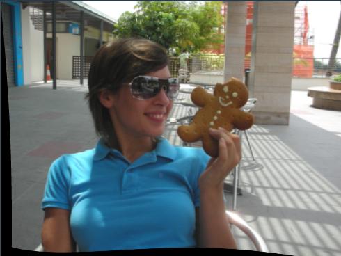
9.12.2.2 Distort example with 2x2 grid
; muSE v2 ; ; My no-kick-butt style. ; This is a pretty useless style that demonstrates a 2x2 grid. (style-parameters) (segment-durations 8.0) (define muvee-global-effect (effect-stack (effect "Perspective" (A)) (effect "CropMedia" (A)))) (define grid2by2 (effect-stack (effect "Distort" (A) (param "GridSize" 2) (param "p00x" -1.0 (linear 0.0 -1.0) (linear 1.0 0.0)) (param "p00y" -1.0 (linear 0.0 -1.0) (linear 1.0 0.0)) (param "p00z" 0.0 (linear 0.0 0.0) (linear 1.0 -3.0)) (param "p11x" 1.0 (linear 0.0 1.0) (linear 1.0 0.0)) (param "p11y" 1.0 (linear 0.0 1.0) (linear 1.0 0.0)) (param "p11z" 0.0 (linear 0.0 0.0) (linear 1.0 -3.0)) muvee-std-segment-captions))) (define muvee-segment-effect grid2by2)
Please note that you only set the coordinates of the points you want to change. If a control point is not added as a parameter, it’s default value is used.
9.12.2.3 The 3x3 grid
If you are using a grid that is 3 by 3, then the grid has a total of 9 points. So the parameters that should be used are:
( p02x,p02y,p02z) ,( p12x,p12y,p12z) ,( p22x,p22y,p22z) ( p01x,p01y,p01z) ,( p11x,p11y,p11z) ,( p21x,p21y,p21z) ( p00x,p00y,p00z) ,( p10x,p10y,p10z) ,( p20x,p20y,p20z)
As can been seen, The point (p00x ,p00y ,p00z) refers to the bottom left of the image and point (p22x ,p22y ,p22z) refers to the top-right of the image.
The default values that must be set for the 3 by 3 grid are:
( -1.0,1.0,0.0) ,( 0.0,1.0,0.0) ,( 1.0,1.0,0.0) ( -1.0,0.0,0.0) ,( 0.0,0.0,0.0) ,( 1.0,0.0,0.0) ( -1.0,-1.0,0.0) ,( 0.0,-1.0,0.0) ,( 1.0,-1.0,0.0)
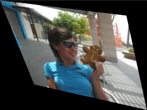
9.12.2.4 Distort example with 3x3 grid
; muSE v2 ; ; My kick-butt style. ; This demonstrates the fish eye effect with a 3x3 grid. (style-parameters) (segment-durations 8.0) (define muvee-global-effect (effect-stack (effect "Perspective" (A)) (effect "CropMedia" (A)))) (define grid3by3 (effect-stack (effect "Distort" (A) (param "GridSize" 3) (param "p11z" 0.0 (linear 0.0 0.0) (linear 1.0 5.0)) muvee-std-segment-captions))) (define muvee-segment-effect grid3by3)
Please note that you only set the coordinates of the points you want to change. If a control point is not added as a parameter, it’s default value is used.
This is a screenshot of the output:
9.12.2.5 The 5x5 grid
If you are using a grid that is 5 by 5, then the grid has a total of 25 points. So the parameters that should be used are:
( p04x,p04y,p04z) ,( p14x,p14y,p14z) ,( p24x,p24y,p24z) ,(p34x,p34y,p34z),(p44x,p44y,p44z) ( p03x,p03y,p03z) ,( p13x,p13y,p13z) ,( p23x,p23y,p23z) ,(p33x,p33y,p33z),(p43x,p43y,p43z) ( p02x,p02y,p02z) ,( p12x,p12y,p12z) ,( p22x,p22y,p22z) ,(p32x,p32y,p32z),(p42x,p42y,p42z) ( p01x,p01y,p01z) ,( p11x,p11y,p11z) ,( p21x,p21y,p21z) ,(p31x,p31y,p31z),(p41x,p41y,p41z) ( p00x,p00y,p00z) ,( p10x,p10y,p10z) ,( p20x,p20y,p20z) ,(p30x,p30y,p30z),(p40x,p40y,p40z)
As can been seen, The point (p00x ,p00y ,p00z) refers to the bottom left of the image and point (p44x ,p44y ,p44z) refers to the top-right of the image. Point (p22x ,p22y ,p22z) refers to the center of the image.
The default values that must be set for the 5 by 5 grid are:
( -1.0,1.0,0.0) ,( -0.5,1.0,0.0) ,( 0.0,1.0,0.0) ,( 0.5,1.0,0.0) ,( 1.0,1.0,0.0) ( -1.0,0.5,0.0) ,( -0.5,0.5,0.0) ,( 0.0,0.5,0.0) ,( 0.5,0.5,0.0) ,( 1.0,0.5,0.0) ( -1.0,0.0,0.0) ,( -0.5,0.0,0.0) ,( 0.0,0.0,0.0) ,( 0.5,0.0,0.0) ,( 1.0,0.0,0.0) ( -1.0,-0.5,0.0) ,( -0.5,-0.5,0.0) ,( 0.0,-0.5,0.0) ,( 0.5,-0.5,0.0) ,( 1.0,-0.5,0.0) ( -1.0,-1.0,0.0) ,( -0.5,-1.0,0.0) ,( 0.0,-1.0,0.0) ,( 0.5,-1.0,0.0) ,( 1.0,-1.0,0.0)
All the above values are the default value set in the Distort effect. So you do not need to explicit set them. :)
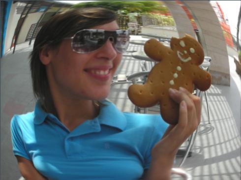
9.12.2.6 Distort example with 5x5 grid
; muSE v2 ; ; My kick-butt style. ; This simple periodic cloth effect. (style-parameters) (segment-durations 8.0) (define muvee-global-effect (effect-stack (effect "Perspective" (A)) (effect "CropMedia" (A)))) (define grid5by5 (effect-stack (effect "Distort" (A) (param "GridSize" 5) (param "p00z" 0.0 (fn (p) (* 0.2 (sin (* 2.0 (* pi p)))))) (param "p01z" 0.0 (fn (p) (* 0.2 (sin (* 2.0 (* pi p)))))) (param "p02z" 0.0 (fn (p) (* 0.2 (sin (* 2.0 (* pi p)))))) (param "p03z" 0.0 (fn (p) (* 0.1 (sin (* 2.0 (* pi p)))))) (param "p04z" 0.0 (fn (p) (* 0.0 (sin (* 2.0 (* pi p)))))) (param "p10z" 0.0 (fn (p) (* -0.2 (sin (* 2.0 (* pi p)))))) (param "p11z" 0.0 (fn (p) (* -0.15 (sin (* 2.0 (* pi p)))))) (param "p12z" 0.0 (fn (p) (* -0.1 (sin (* 2.0 (* pi p)))))) (param "p13z" 0.0 (fn (p) (* -0.05 (sin (* 2.0 (* pi p)))))) (param "p14z" 0.0 (fn (p) (* -0.0 (sin (* 2.0 (* pi p)))))) (param "p20z" 0.0 (fn (p) (* 0.5 (sin (* 2.0 (* pi p)))))) (param "p21z" 0.0 (fn (p) (* 0.1 (sin (* 2.0 (* pi p)))))) (param "p22z" 0.0 (fn (p) (* 0.1 (sin (* 2.0 (* pi p)))))) (param "p23z" 0.0 (fn (p) (* 0.0 (sin (* 2.0 (* pi p)))))) (param "p24z" 0.0 (fn (p) (* 0.0 (sin (* 2.0 (* pi p)))))) (param "p30z" 0.0 (fn (p) (* 0.2 (sin (* 2.0 (* pi p)))))) (param "p31z" 0.0 (fn (p) (* 0.2 (sin (* 2.0 (* pi p)))))) (param "p32z" 0.0 (fn (p) (* 0.2 (sin (* 2.0 (* pi p)))))) (param "p33z" 0.0 (fn (p) (* 0.1 (sin (* 2.0 (* pi p)))))) (param "p34z" 0.0 (fn (p) (* 0.0 (sin (* 2.0 (* pi p)))))) (param "p40z" 0.0 (fn (p) (* -0.2 (sin (* 2.0 (* pi p)))))) (param "p41z" 0.0 (fn (p) (* -0.2 (sin (* 2.0 (* pi p)))))) (param "p42z" 0.0 (fn (p) (* -0.2 (sin (* 2.0 (* pi p)))))) (param "p43z" 0.0 (fn (p) (* -0.1 (sin (* 2.0 (* pi p)))))) (param "p44z" 0.0 (fn (p) (* -0.0 (sin (* 2.0 (* pi p))))))) muvee-std-segment-captions)) (define muvee-segment-effect grid5by5)
This is a screenshot of the output: